KLEMM drilling methods
A profound understanding of the manufacturing and drilling processes is required in order to develop optimised machinery and tools for special foundation industry. At KLEMM Bohrtechnik, this expertise flows directly into the products.
Production and drilling methods
Grouted anchors
Production sequence
Drilling of the borehole by using a drilling method adapted to the boundary conditions (type of ground, groundwater, adjacent buildings ...).
Extraction (pulling) of the drill rods after or during the filling and grouting with cement and installation of the anchoring tendon.
Subsequent grouting of the anchor. Increased suspension pressure causes the grout body to burst open. The resulting cracks or fissures are post-grouted, if necessary several times with cement supension.
Acceptance testing and fixing of the anchors. The steel tendon is tensioned by a hollow piston jack beginning with a high pressure test load. In stepped load cycles, it is tensioned and released down to the design load several times. At each stage the time-dependent settling behaviour ("creeping") of the grout body in the subsoil and the elastic behaviour of the free tendon length are recorded.
If the creep of the component reaches a steady state and the required free tendon length is satisfactory then the tendon is finally fastened and wedged in place using the anchor head plate. A test protocol is prepared for every anchor. Protruding strand ends are removed and the anchor head is covered by a cap. This completes the manufacturing process of the anchor.
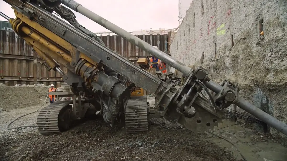
Production of ground achors on a construction site

Drilling methods
There are various methods of producing a drilled hole. At the time of the invention of the grouted anchor it was mainly ramming a pipe with lost drill bit, thus dispacing the soil. For non-cohesive soils pipes with an external diameter of 76 mm were very widely used. The rotary drilling method with staged drill bits or roller bits was used in cohesive soils. Higher anchor forces and additional post grouting pipes mounted on the tension member soon made greater drilling diameters necessary. The expansion of the traffic routes called for even more stabilisation of slopes with extremely long permanent anchors - and this too placed more demands on the drilling depths. These could range from 40 to 60 m, and in exceptional cases even 100 m. This exceeded the depths achievable at the time with ramming of about 20 m, and with a compressed air driven rotary percussion to around 30 m. Pure flushing bore methods - as generally used in water well drilling - couldn’t tackle this due to the associated fine soil washout and risk of subsidence.
Back then a new process and drilling tools were developed by KLEMM Bohrtechnik, for example for overburden drilling with a hydraulic drifter. The term overburden drilling comes from the fact that the outer casing and drilling rods first move together through all material (loose soil including rock) that overlays the bedrock horizon. As soon as solid rock is met, the outer casing is left in place and drilling is continued with just the drilling rods. Today the expression overburden drilling is used for almost all drilling where loose soil with rock is found near the surface.
The limits of classic overburden drilling are determined by the presence of intercalating loose and firm rock formations because the casing advanced by rotation only cannot get through rock shelves and in addition loose rock layers below the shelf normally collapse.
This problem was resolved using the double-head drilling procedure. The outer casing contains its own casing crown and the drill rods rotated in opposite directions and were driven forward by a hydraulic drifter. This was a crucial step forward, particularly for intercalation drilling. In addition, this drilling system made it possible to drill through sheet-pile walls, diaphragm walls and bored pile walls even at high external water overpressure and, in this way, reliably prevent water and soil deprivation and hence hazardous settlement in the excavation pit environment during the entire production process for the anchor.
Recently, new ways have been developed in special foundation indudstry where, for some dedicated geologies, the impact movement of the chosen overburden drilling method is replaced by a vibrating movement. The noise level can be considerably reduced and the downward speed is further increased by overcoming skin friction, especially during the retraction of the drill rods. The rotary movement during retraction can also be dispensed with, thus avoiding torsion of the steel tendon.
Drilling methods
with a single rod
with auger rods
with a hydraulic drifter and a single rod and lost bit
with hydraulic drifter and double rod
rotary / rotary with double head drilling equipment and down-the-hole-hammer
rotary / rotary percussion with double-head drilling equipment
Applications
Increase the load-bearing capacity of the foundation soil.
Anchoring of a construction pit wall (pile wall, diaphragm wall, sheet pile wall, shored construction pit, ...).
Horizontal consolidation of the foundation soil to compensate for settlements that occur as a result of tunnel excavation. Applied where vertical access is not possible in densely built-up areas.
Sealing or backfilling of fissured or karstic, usually rocky subsoil, e.g. in the construction of dams and underground structures.
Production of deep-lying, gap-free sealing bases in sand and gravel.
Improving the bearing capacity of a mostly loose subsoil by compacting it without breaking it up.
Temporary anchors
Temporary anchors, fully or partially removable, are used to secure construction projects, e.g. retaining walls for a lifetime of a maximum of two years.
Permanent anchors
Permanent anchors are grouted anchors with a service life from two years and beyond and are therefore part of the construction structure. The sheathing tubes of the strands and each cavity of the anchor head are filled with permanently plastic corrosion protection compound.
